RECHERCHE PAR INSPIRATIONS


- Shock absorbers
- Thermal bands
- Aluminum boxes
- Back Buckles
- Bubbles
- Blinkers
- Dressers
- Counters
- Back shells
- Exhausts
- Rear lights
- Air filters
- Forks
- Mudguards
- Handlebars
- Brake and clutch levers
- Side plates
- Handles
- Headlights
- Footrest
- Tanks
- wing mirror
- Saddles
- Silent
- Fork gaiters
- Insurance carriers
- License plate brackets
- Shock absorbers
- Thermal bands
- Aluminum boxes
- Back loops
- Blinkers
- Dressers
- Counters
- Exhausts
- Rear lights
- Air filters
- Forks
- Mudguards
- Handlebars
- Brake and clutch levers
- Side plates
- Handles
- Headlights
- Footrest
- Tanks
- Wing mirror
- Engine guard
- Saddles
- Silent
- Fork gaiters
- Insurance carriers
- License plate holders
- Shock absorbers
- Thermal bands
- Aluminum boxes
- Back loops
- Bubbles
- Blinkers
- Dressers
- Counters
- Back shells
- Exhausts
- Rear lights
- Air filters
- Forks
- Mudguards
- Handlebars
- Brake and clutch levers
- Side plates
- Handles
- Headlights
- Footrest
- Tanks
- wing mirror
- Saddles
- Silent
- Fork gaiters
- Insurance carriers
- License plate holders
- Shock absorbers
- Thermal bands
- Aluminum boxes
- Back loops
- Blinkers
- Dressers
- Counters
- Exhausts
- Rear lights
- Air filters
- Forks
- Mudguards
- Handlebars
- Brake and clutch levers
- Side plates
- Handles
- Headlights
- Footrest
- Tanks
- wing mirror
- Engine guard
- Saddles
- Silent
- Fork gaiters
- Insurance carriers
- License plate holders
RECHERCHE PAR MARQUES DE MOTO


Digital counter assembly
Digital counter installation
1. Connection of wires
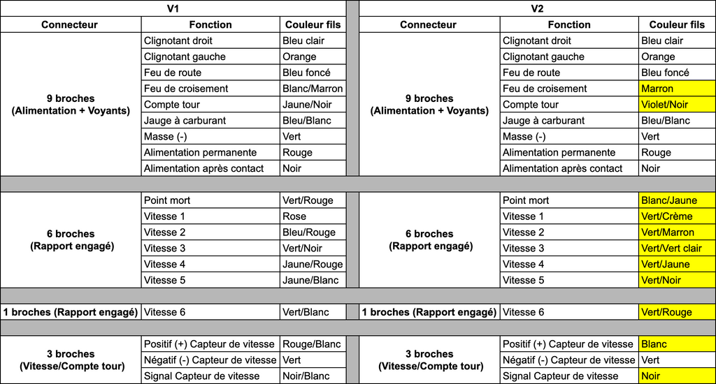
In yellow in the table = difference between V1 & V2
2. Installation
Account round
The tour (black and yellow thread) is to be installed at the negative output of the coil.
Example CB650 of 1979:


If this does not work in this way (as on the BMW K100 for example), It must be installed as follows:

Kilometric counter (version without cable only)

You have to install the probe on a support (the caliper for example) and install the magnet (s) on the disc. It is best to install the magnets as close as possible to the sensor (+/- 2 mm).
3. Configuration
Make the menu
To reach the adjustment menu, you have to lock the button for 3 to 5 seconds and then contact.
Try longer in case of failure.
If the problem persists, check the assembly and the connections between the permanent + and the + after contact.
Demonstration video "reach the menu"
The menus
There are 4 menus. The speed display tells you in which level you are located.
Menus videos:
1. adjustment of the circumference:
In the first level of adjustment.
The mileage indicates “CCC ---”.
XXX means the default wheel circumference.
How to define the circumference? The scope of the wheel must be calculated.
Calculation of the perimeter of a circle:
P = 2 x  x radius (in mm)
Radius = axis of the wheel at the end of the tire.
Note: If during the test the counter to an error of 5 to 10% it is necessary to add 5% to this result (p*1.05)
Once calculated, you can enter the data.
The number of thousands will flash at the time, press briefly to change the current number.
After a few seconds, the device automatically switches to the hundreds, then dozens.
Its range is 50 ~ 2600mm.
Keep the button pressed for 3 seconds to save, then enter the adjustment zone 2.
2. The number of cylinder
In the second level of adjustment.
It is indicated: "Y2".
2 means that the number of engine cylinders is 2.
3 corresponds to 3 cylinders
4 corresponds to 4 cylinders ...
Pressing the key allows you to adjust the number of cylinder.
Keep the button pressed for 3 seconds to save.
3. Fuel gauge adjustment
It is indicated to the right the value 1 or 5.
1: Indicates the use of a 2 -wire sensor.
5: Indicates the use of a 3 -wire sensor.
Hold the button for 3 seconds to record, then enter the authorized mileage adjustment area.
To choose according to the resistance model of your motorcycle.
If you do not have a fuel gauge sensor, the landing of the fuel gauge (blue and white) will make the fuel gauge stop flashing.
For others, you must put it in the ground via a resistance of 30 to 500 ohms.
Everything that is more or less common has no effect. 500 ohms displays 1 bar (out of 8) or almost empty. 30 ohms 8 bars display (full screen). (About 330 ohms is half full, etc.) So if the land wire is not working for you, try to put it in the ground through resistance between 30 and 500 ohms.
Fuel gauge sensor (example: Royal Enfield):

4. Accumulation of speed
The basic position is "F03.4"
F = the frequency, which is used to change the speed
Once the meter adjustment is finished, press the button for a long time to save and leave the menu.