RECHERCHE PAR INSPIRATIONS


- Shock absorbers
- Thermal bands
- Aluminum boxes
- Back Buckles
- Bubbles
- Blinkers
- Dressers
- Counters
- Back shells
- Exhausts
- Rear lights
- Air filters
- Forks
- Mudguards
- Handlebars
- Brake and clutch levers
- Side plates
- Handles
- Headlights
- Footrest
- Tanks
- wing mirror
- Saddles
- Silent
- Fork gaiters
- Insurance carriers
- License plate brackets
- Shock absorbers
- Thermal bands
- Aluminum boxes
- Back loops
- Blinkers
- Dressers
- Counters
- Exhausts
- Rear lights
- Air filters
- Forks
- Mudguards
- Handlebars
- Brake and clutch levers
- Side plates
- Handles
- Headlights
- Footrest
- Tanks
- Wing mirror
- Engine guard
- Saddles
- Silent
- Fork gaiters
- Insurance carriers
- License plate holders
- Shock absorbers
- Thermal bands
- Aluminum boxes
- Back loops
- Bubbles
- Blinkers
- Dressers
- Counters
- Back shells
- Exhausts
- Rear lights
- Air filters
- Forks
- Mudguards
- Handlebars
- Brake and clutch levers
- Side plates
- Handles
- Headlights
- Footrest
- Tanks
- wing mirror
- Saddles
- Silent
- Fork gaiters
- Insurance carriers
- License plate holders
- Shock absorbers
- Thermal bands
- Aluminum boxes
- Back loops
- Blinkers
- Dressers
- Counters
- Exhausts
- Rear lights
- Air filters
- Forks
- Mudguards
- Handlebars
- Brake and clutch levers
- Side plates
- Handles
- Headlights
- Footrest
- Tanks
- wing mirror
- Engine guard
- Saddles
- Silent
- Fork gaiters
- Insurance carriers
- License plate holders
RECHERCHE PAR MARQUES DE MOTO


Installation of 2.0 switches
Wire Function & Matching:
Left switch:
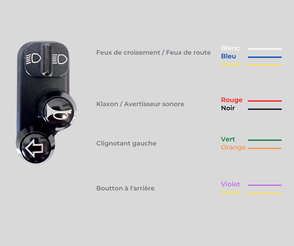
Right commodo:

Connecting the indicators with the “Multi Flasher Relay” module

Installation video:
(Shortly)
The user manual
This user manual only applies to commodos REMMOTORCYCLE. It contains important notes about safety and handling. Read the instructions carefully, especially the safety instructions, in theircompletely before using the switching unit on your vehicle. Failure to follow these instructions may result in vehicle damage, impair road safety or cause accidents.
Please keep these instructions for future use. If you transfer the unitswitching to a third party, please forward these instructions for use to the appropriate person.
Security
Intended use
REMMOTORCYCLE 2.0 switches for 22 mm motorcycle handlebars are used for indirect control of functions of the vehicle's electrical circuits via an electronic control module, e.g. Axel Joost for the indicator function.
THEcharacteristics ofpush buttons :
250VAC 3A - IP45
The characteristics of the switches:
0.5A 50V DC; Resistance: 30mΩ Max, Insulation Resistance: 100mΩ Min at 500V DC; Withstand voltage: AC 500V for 1 min
The controls are universal. Mounting possibilities depend on compatibility with the handlebars and other electronic components.
Safety instructions
This product represents a danger for children and people with reduced physical, sensory or mental capabilities (e.g. partially disabled people or elderly people with restricted physical and mental capabilities) or people who do not have not have the required experience or knowledge (e.g. older children).
Keep the packaging film and small parts of the supplied equipment out of the reach of children. Risk of asphyxiation.
Risk of short circuit
The electrical installation and mechanical assembly on the vehicle must be carried out in accordance with the regulations. Incorrect installation can lead to short circuits or malfunctions of the on-board electrical system.
When installing, always follow the information contained in the vehicle's operating instructions or in a maintenance and repair manual corresponding to the model, as well as the vehicle manufacturer's specifications and the operating instructions for the control module used.
Before carrying out work on the vehicle's electrical system, always disconnect the vehicle's battery.
No tensile force should be exerted on the electrical cables, even when the steering is fully turned. They must be passed in such a way as to be protected, not to be stuck and not to suffer friction or bending.
Risk of injury
During assembly work, ensure that the vehicle is perfectly stable and that the workplace is well lit.
Assembly
Preparation
Raise your vehicle safely (using a workshop jack stand or the vehicle's center stand) in a clean, well-lit area. The battery must be disconnected before starting work (unplug the minus cable).
Assembly
- Remove the handles, throttle grips and old commodos.
- Loosen the two M3 screws on the switches. The two parties must remain linked.
- Slide the controls into place.
- You can tighten the M3 screws on the back of the switches.
- Connect the cables to the motorcycle's electrical harness using the connection diagrams at the top of the page.
Risk of short circuit!
Connect the switching unit in accordance with the corresponding connection diagram as well as the connection diagram of the control module of the electronic button control. To do this, carefully follow the instructions contained in the assembly instructions for the electronic button control. Assign the plus and minus terminals to the corresponding controlled function according to the diagrams.
Once the cables are connected, the disconnected battery must be reconnected. The controlled electrical functions of the vehicle can now be checked.
Storage
Store the unassembled switching unit in the original packaging in a closed room protected from weather and humidity.
Cleaning and maintenance
Clean the switch unit with warm soapy water or a motorcycle cleaner and a soft cloth. Never use a cleaning product that can attack aluminum.
Legal guarantee
This product is covered by the two-year legal warranty. The warranty period begins from the date of purchase. Any sign of wear, any improper use or for purposes other than those intended, any damage due to an accident, manipulation or attempted repair by unauthorized customer service or person or any product modified on the technical plan are excluded from the guarantee.
Contact
If you have any questions regarding the product and/or these instructions, please contact our after-sales service center by email at the following address before using the product for the first time. contact@remmotorcycle.com
We will help you as soon as possible. In this way, we together guarantee the correct use of the product.